Garage Wiring

Associate
Joined
28 Sep 2011
Posts
102
Location
Stratford-upon-Avon
House wiring now all done and happy with, decided to move on to the garage.
The garage is detached from the house and has a single power feed coming in to a fused switch used to operate the lights. The power supply for the plug sockets are also coming from this area, but is always on and not determined by the switch.

As the switch is on the far wall, I have to stumble over everything to get to it, so I decided to install a second switch close to the door I use.
Having wired a few 2 way switches now, thought it to be a simple job, unfortunately things went down hill when I opened the fused switch to connect the cables up.
No standard switch markings (Com, L1, L2). Instead it has Supply L & N and Load L & N and earth.

Following the wire from the existing light circuit, the light comes in on a 2 Core + Earth with the "Brown" cable going to "Load L" and "Blue" cable going to "Load N".

I have run a 3 core + Earth from the new switch, but now not sure where it should be connected to?
Earth is easy.

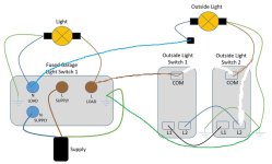
Here is a picture of the Fused switch (Without the new switch cables)


Any advice where the "Com", "L1" and "L2" cables should go?
 
Man of Honour
Joined
19 Nov 2002
Posts
18,961
Location
Over land and sea.
That's just a standard fused connection unit, you can't use that as a 2 way switch.
The easiest thing to do would be to just run the Load to the new switch & back just using that switch to operate the lights.
You need to keep the FCU as it looks like the lights are fused down from the sockets.
 
Associate
Joined
20 Oct 2012
Posts
457
Location
west sussex
Take a cable from the load side and goto 1st switch this will supply the 2way lighting so you will also have to re wire the light back to the same switch the feed comes from, so you will have 3 cables at the 1st switch. 1 from FCU, 1 to light(s) and the 3rd being the 3core to the 2nd/3rd/4th switch etc.
Hope that makes sense.
 
Associate
OP
Joined
28 Sep 2011
Posts
102
Location
Stratford-upon-Avon
Also, Iv added a spot light to the front of the garage and need to power it and have 2 switches. One switch (#1) located outside and another switch (#2) inside the garage.

Iv already run some 3 Core + E between the switches and connected the light to the indoor switch (#2). (The indoor switch is closest to the light, the outdoor switch is closest to the supply)

I guess I will need to connect the Light to the supply for a Neutral connection?

Currently I have just terminated the N from the light in a choc block and wired up as below.


Do I run the "L Load" from the fused switch to "L1" on Switch 1, Earth -> Earth and then I guess I need to connect "N Load" to the new lights Neutral?
 
Associate
Joined
22 Mar 2004
Posts
701
LEQlcQs.jpg

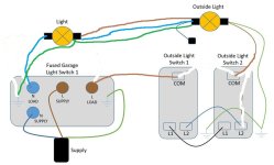
I think it would be more like that.

But the fused spur would be a master switch for the external lights i.e when the fused spur is switched off then all the lights would be isolated.

You probably wouldn't be able to connect to the live side of the fused spur. It would depend on the size of protective device protecting the circuit and the size of cable you are feeding the new lighting circuit, probably 1.5mm, which depending on the way it is installed (clipped direct?) might only be designed to take around 16amp.

would this be more like it?

Apologies for the crude editted diagrams, but that would control all outside lights from the 2 way switching. If you want the existing light switched seperately, you could put in a 2gang switch.

Hp2wgqY.jpg
 
Associate
Joined
17 Oct 2010
Posts
1,073
You want to start from scratch and list what lights you want and what you want them to be able to do - then we can advise how to wire it all up.

Forget using the fuse spur as any kind of light switch - just use it as a 3/5A supply for the lighting only.

Assuming basic setup for 1 inside light with 2 way switching just run 1.0mm cable from the load side of the fuse spur to the 1st 2 way switch, put the live into L1 and neutral into connector block in backbox, then take a 2nd 1.0mm from 1st switch to light fitting - put live from this into L2 then neutral into connector, light fitting end just connect up live neutral earth etc

Then take 3 core from this switch to the 2nd 2 way switch and terminal both ends the same so com,L1,L2, brown,black,grey both ends. sorted.

you can also wire this other ways that may be neater and have just 3 core at the switches and all connections at the light fitting, might look neater

Ouside lights i would ideally take a 2nd feed from supply side of the existing the fuse spur in 2.5mm into another fuse spur for the os lights so they can be isolated separately for when they let water in or become faulty.
 
Associate
Joined
17 Oct 2010
Posts
1,073
Just read your op properly

If you just want to add the 2nd switch only ...

Get a 2nd metal backbox & metal 2 way switch to match existing spur
Take the knock outs out for both of these on the left or right side
Mount the new backbox on the wall next to the fuse spur

Pull the 3 core down the conduit into the fuse spur backbox then through the knockouts to the new backbox
Terminate this into the new 2 way switch, same terminals as the other end

Take a 1.0mm cable from fuse spur backbox through to new switch backbox next to it through the knock outs

brown from this connect to live load from spur and L1 at switch

blue from this sleeve brown as switch live both ends and connect to L2 at switch end and connect to the brown for light that originally came from the spur live load at spur end with connector block

Now should work as 2 way switch
 
Last edited:
Back
Top Bottom